


Gas turbine engines play a crucial role in powering various industries, from aviation to power generation. With their efficient design and reliable performance, these engines have revolutionized the way we travel and generate electricity. In this article, we will explore the inner workings of a gas turbine engine, discuss different types, highlight their advantages, and examine their applications across industries.
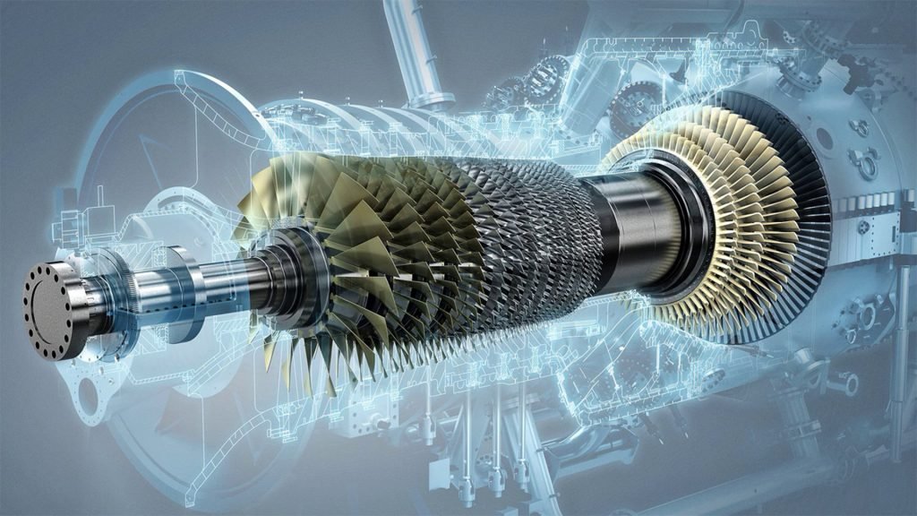
Table of Contents
What Is A Gas Turbine Engine?
Any internal combustion engine that uses gas as the working fluid to turn a turbine is referred to as a gas-turbine engine. Additionally, a full internal combustion engine, including at least a compressor, a combustion chamber, and a turbine, is referred to by this phrase.
Gas turbine engines have been used in cars, including prototype cars, for over 60 years. These engines are most frequently associated with the loud noise they cause at the rear of a cross-country commercial aircraft. You would be correct if you thought it was a horrible idea to power your everyday automobile with a noisy 50,000 RPM fan blade.
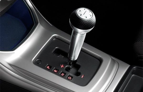
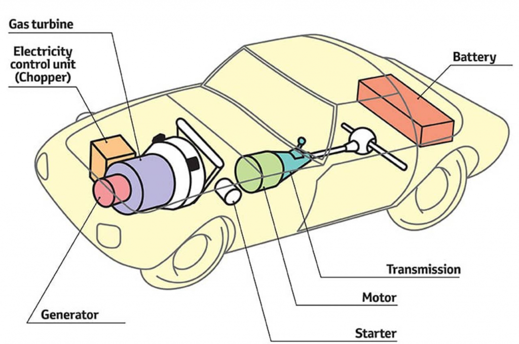
In most cases, turbines were used in one of two ways for automotive purposes. They may utilize a hybrid system, in which the turbine drives the car’s system of electric motors, or a direct-drive system, in which the engine powers the wheels directly through a gearbox.
Even though complexity is a problem, several manufacturers of various sizes have been working to spread the word about innovative technology. The crew from The Drive is here today to help you comprehend how these undeniably interesting failed ventures aimed to alter the automobile world.
Gas turbine engines come in various shapes and sizes. Still, they always have three basic components: a compressor fan to compress incoming air to high pressures, a combustion chamber to burn fuel to power the system, and a turbine to turn the fuel into steam.
A gas-turbine engine can provide useful labour or propulsion force. A pure jet aircraft engine can create thrust by speeding up the turbine exhaust flow through a nozzle and driving a generator, pump, or propeller. For the same output, such an engine is substantially smaller and lighter than a reciprocating internal-combustion engine and may produce large quantities of power.
Reciprocating engines rely on a piston’s up-and-down motion, which must then be converted to rotary motion by a crankshaft arrangement, in contrast to gas turbines, which offer direct rotary shaft power. Although the gas-turbine engine is a theoretically straightforward technology, due to the high temperatures and strains experienced during operation, the components for an efficient unit must be carefully developed and made from expensive materials. Therefore, gas-turbine engine installations are often restricted to big units that are financially viable.
How Does a Gas Turbine Engine Work?
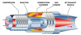
Through the use of a shaft, the turbine is coupled to the compressor. While a result, as the turbine turns and fuel burns, the compressor actively draws in additional air and pushes it into the combustion chamber, maintaining power. It has a similar design to a turbocharger. Still, it is self-contained and not dependent on external airflows, such as the exhaust gases from an operating engine.
Since they are employed in civilian aircraft, turboprop and high-bypass turbofan applications are where people most frequently encounter turbine engines. Because the high-pressure combustion chamber produces high-speed exhaust gas as a by-product, which may be used for propulsion, they are ideally suited to flight applications. Modern military jet fighters commonly employ low-bypass turbofans. After the turbine, these turbines are frequently connected to a second fuel injection and combustion chamber.
Whatever their intended purpose, turbines are frequently used in flight due to their great compression, which excels even in the thinner air kilometres above the Earth. Their high thrust enables more efficient fuel use, and their constant operating speed is suitable for cruising at altitudes for extended periods.
Why Use a Gas Turbine Engine?
There are strong reasons to think about using turbine motors on the ground. The first is that they are potentially more dependable since they have fewer moving parts than a piston internal combustion engine.
The second factor is the power band of gas turbines, which allows for ridiculously high torque at low RPMs from a very tiny device. Gas turbines have remained popular in diesel-electric railway locomotives, as strong torque is valued for starting large consists.
The last justification is that they can frequently run on almost any fuel, including tequila, in the instance of the President of Mexico and his Chrysler Turbine technology display in the 1960s (you know you just heard the song in your mind, too).
What Models Currently Feature Gas Turbine Engines?
Production automobiles do not currently use gas turbine engines. Jaguar’s CX75 concept, which employed diesel-fueled micro-turbines to power an electric hybrid system, came the closest to going into production recently. However, as the financial crisis worsened, The car was left behind.
The only terrestrial vehicle for use on roads that is for sale is the aforementioned Y2K Superbike. However, these are constructed to order, and only a few numbers are produced annually.
Major components of gas-turbine engines
Compressor
Centrifugal compressors, which are very straightforward and affordable, were used in early gas turbines. However, they are constrained to low-pressure ratios and fall short of the efficiency of contemporary axial-flow compressors. As a result, today’s centrifugal compressors are mostly found in small industrial units.
Axial-flow compressors work in the opposite direction than reaction turbines. The blade passageways must force the fluid in a tangential direction, which resembles twisted, sharply curved airfoils. One side of the blade must be under more pressure than the other. An increase in pressure for subsonic flow necessitates an increase in the flow area, which lowers the flow velocity between the blade passageways and diffuses the flow.
It is necessary to think of a row of compressor blades as a collection of sparsely spaced, sharply curved airfoil structures with which airflow interacts aggressively. In addition to increased pressure along the blades, there will also be a difference in pressure between them. Losses in a real unit are caused by flow friction and leakage wakes left by earlier sets of blades, secondary circulation, and swirl flows. The actual blade configurations in a rotating assembly must be tested using specialized test settings or rigs, as opposed to tests of stationary blade assemblies, often known as cascades.
In addition to having the proper aerodynamic form, blades must be light and resistant to dangerous vibrations. The development of compressor (and turbine) blades has recently benefited from sophisticated computer algorithms.
Only very minor pressure increases can be managed by a compressor stage, which normally has pressure ratios per stage of 1.35 or 1.4 to 1 in a modern design. Still, significant expansion-pressure ratios may be obtained in a reaction-turbine stage. Thus, more steps are needed for compressors than for turbines.
The flow will tend to split from the blades if greater stage pressure ratios are attempted, which will cause turbulence, a decrease in pressure increase, and a “stalling” of the compressor with a simultaneous loss of engine power. Regrettably, compressors operate most effectively near this so-called surge situation, where even minor interruptions can cause problems. Maintaining high efficiency without stopping the compressor is still a significant issue for the designer.
The volume of the air reduces as it is compressed. To keep the through-flow velocity almost constant, the annular passage area must likewise decrease, meaning that the blades must shorten at increasing pressures. It is frequently necessary for the rotating speed of the front, low-pressure end of the compressor to be slower than the rear, high-pressure end to achieve the best balance of blade-tip speeds and airflow velocities.
Large aviation gas turbines achieve this with the use of “spooled” shafts, in which the low-pressure end shaft, which is powered by the low-pressure section of the turbine, runs at a separate speed inside the hollow high-pressure compressor/turbine shaft, with each shaft having its bearings. Engines with twin and triple spools have both been produced.
Combustion chamber
The air must first slow down to separate the two streams of air exiting the compressor. A zone where atomized fuel is injected and burns with a flame kept in place by a turbulence-producing barrier is supplied centrally from the smaller stream. Reduce the overall temperature to a value suitable for the turbine intake; the bigger, cooler stream is delivered into the chamber through perforations along a “combustion liner” (a shell).
A single circular tube with fuel-injection nozzles positioned circumferentially or some approximately cylindrical components spread around the circumference of the engine for combustion. Longer combustion chambers with some internal reversed flow can make it easier to achieve almost uniform exit-temperature distributions in stationary applications than in short aeroplane combustion chamber
Turbine
The turbine is typically built on the reaction principle, with hot gases expanding through one or two spooled turbines in up to eight stages. A high-pressure turbine that drives the compressor usually performs part of the expansion in a turbine that drives an external load. In contrast, a separate, “free” turbine linked to the load performs the remaining expansion.
The majority of high-performance aircraft engines have numerous spools. Two high-pressure turbine stages power 11 high-pressure compressor stages on an outer spool that rotates at 9,860 revolutions per minute in a recent large aircraft engine design. In contrast, four low-pressure turbine stages power the fan for the bypass air, and four additional low-pressure compressor stages through an inner spool that rotates at 3,600 revolutions per minute (see below). Three to five total turbine stages are more usual for fixed systems.
Special metallic alloys must be used for the turbine blades due to high centrifugal blade stresses and temperatures at the turbine intake. Sometimes, such alloys are formed as single crystals. Additionally, cooler air is extracted directly from the compressor and delivered through internal channels to cool blades prone to extremely high temperatures.
Two processes are currently used:
(1) Jet impingement on the inside of hollow blades, and
(2) Bleeding of air through tiny holes to form a cooling blanket over the outside of the blades
Control and start-up
Maintaining the same speed in a gas turbine engine operating an electric generator regardless of the electrical load is necessary. The engine speed can be maintained using less fuel to meet a drop in load from the design limit. Reduced fuel flow will decrease the combustion chamber’s exit temperature and, therefore, the turbine’s available enthalpy drop. Although the compressor handles the same air volume, this has little impact on the turbine efficiency. In contrast to a steam turbine, which must adjust its mass flow rate to accommodate changing loads, the control approach described above is very different.
Controlling a gas-turbine engine for an aeroplane is more challenging. As the aircraft’s altitude and speed fluctuate, the necessary thrust and engine speed may need to be adjusted. Lower air-inlet temperatures and pressures and a corresponding decrease in the engine’s mass flow rate are caused by higher altitudes. Modern aircraft utilize sophisticated computer-driven systems to regulate fuel flow and engine power while monitoring all essential variables.
Gas turbines need an external motor to start up, which might be an electric motor or, for stationary applications, a small diesel engine.
Other design considerations
Only a few instances of the numerous other factors that go into designing a contemporary gas-turbine engine may be provided. Particularly in a multipole unit, careful consideration must be given to the design of the thrust bearings that absorb axial forces and the lubrication system. Components elongate or “grow” as an engine starts and heats up, influencing seals and passage clearances. Bleeding air from the compressor and piping it for turbine-blade cooling or driving accessories are additional factors to consider.